- This web page was last updated on
Wed, 2014 Mar 26 @ 1455 hours
- Questions about this page?
Contact us by email.
As we do more and more projects and look back across them we see an enormous waste of time, money and pcboard real estate on
in circuit programming interfaces. They are duplicated over and over on each and every project board. 75% or more of them are used
once and then rarely again. Wulfden is now offering a series of very inexpensive, easy-to-plugin and easily removed TTL to RS232 Serial level
adapters that can be used as programming adapters for many of the popular MCU platforms. Thses are offered in kit form as
well as assembled and tested
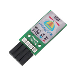
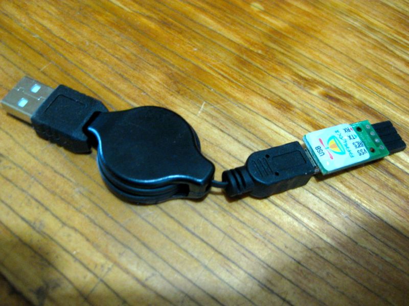
Parallax "Propeller Plug"
- an FTDI FT232R-based USB to TTL Serial Adapter
optimized for program loading the Propeller
Comes with retractable USB A to mini-B cable
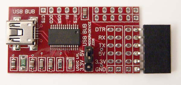
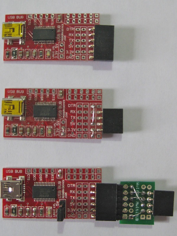
Modern Device "BUB"
- an FTDI FT232R-based USB to TTL Serial Adapter
The USB BUB board has been engineered to be an affordable, flexible
USB connector with lots of applications. It uses the popular FT232R chip, the same as
Arduinos, the FTDI cable we sell, and the Spark Fun breakout boards. The BUB is shipped
assembled and tested as a semi-kit. It comes with two six pin right angle socket connector. The 3
pin header for 5v/3V selection is included but not installed ... by default 5v operation
is selected. As such it is a direct replacement for the familiar FTDI TTL-232R5 cable,
except that the reset pulse is flagged by the DTR signal instead of the CTS signal (as
on the FTDI cable), eliminating a minor glitch from the Windows OS.
You may also purchase the Multi-BUB kit (see below) with a small assortment of connectors
that you may install in order to assemble your own adapters
This board has a few features not found on some
other USB boards though.
- An inductor to filter some high frequency noise from the
power line
- A polyfuse to protect the USB line from short circuits
- An LED which shows serial activity on both the TX and RX lines
- An optional shunt to switch the logic levels from 5 to 3.3 volts.
If the 3 pin header and shunt is left out it logic defaults to 5 volts.
Caution, this shunt doesn't switch the power. While the 3.3 V pin from the
FT232R is available please remember that it's only good for 50 mA of current.
Maybe a future version will feature a 3.3 V regulator too.
- Two sets of header sockets, both of which can be remapped
by the user. One pin header comes connected in the pin order of the
FTDI RS232 cable (the same as the BBB/RBBB/LilyPad/Arduino Pro pin
header, with the added bonus of having the DTR line instead of having
to use the RTS line (and its attendant quirks).
- The other socket is unmapped and is available for the user to remap
in any convenient manner, so you basically get two adapters for the
price of one. Map one for 3.3V and the other for 5V projects. Remap
one for a Basic Stamp, or breadboard Arduino or anything that comes
up.
- The main header can also be easily remapped should one wish, by cutting
the traces and adding jumpers for the required pin order.
- The BUB could be used as a general TTL-Serial converter for any processor.
- The USB-BUB manual, last
updated on Sun, 2012 Jul 22 @ 1854 hours
is available.
- I strongly suggest visiting the FTDI website and downloading the
most recent drivers for Windows or MacOSX. Here is the link to the
FTDI Drivers Page
- If you have a Linux computer, and you have a 2.6 kernel, the driver for the FTDI USB chips is built-in and you are
good to go. You can always run uname -a to get the kernel version.
- To purchase a BUB see below
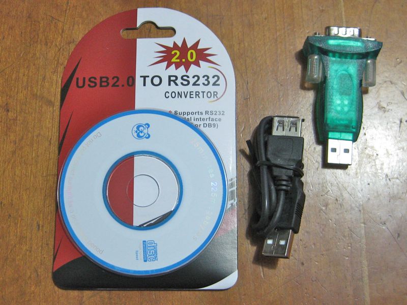
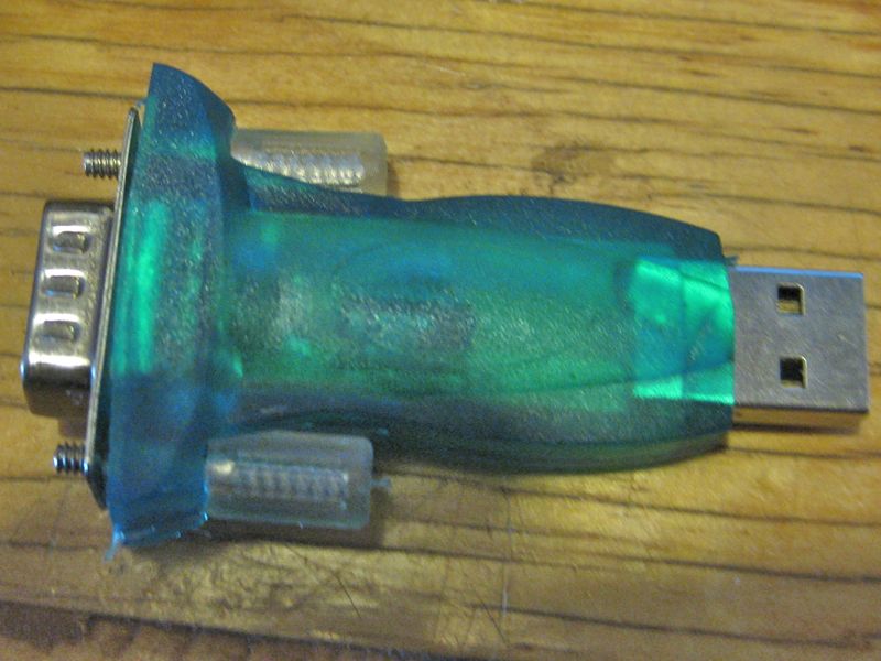
U2 - a USB to RS232 adapter - assembled with cable
- Imported from China - a simple PL2303 chipset based USB (2.0) to RS232 dongle. It comes complete with 12-14"
USB A-Male to A-Female extension cable, and a mini-disk with drivers.
- Works with Windows, MacOSX, and Linux. In house, here at Wulfden, it has been used with Arduino (Win and Mac),
Parallax Propeller Tool (Win), Brads Spin Tool (Mac), Parallax Stamp Editor (Win), MacBS2 (Mac)
- DRivers for Mac OSX and various Windows platforms can be found in my
downlaods/drivers folder.
- To purchase a U2 see below
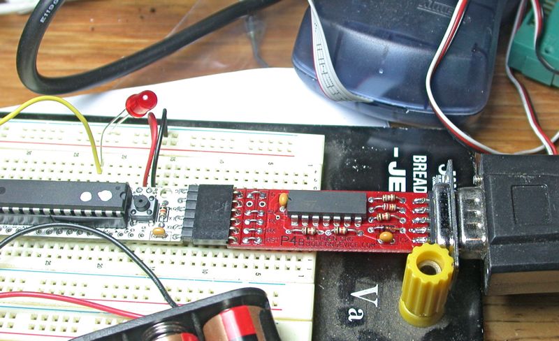
P4/P4B - Serial TTL-to-RS232 Adapter/Programmer (rev 1.0) with DTR Support
- easy assembly, goes together in 5 minutes.
- The P4 was developed jointly by Wulfden and Modern Device Company (of Providence, RI) and has now been superceded by the P4B
- One major feature of the P4/P4B adapter board is that the five/six connector positions are configured with three rows of
five/six holes so that the traces can be cut (on the P4) between two rows and wire jumpers used to rearrange the order of
the TX, RX, Gnd, +5v and DTR
- While the P4 can be used with any processor, the pinout matches for direct plugin as a programming
adapter on a Wulfden Dorkboard Kit and the remaining supply of P4's
is nominally dedicated to the Dorkboard
- The P4B has superceded the P4. It has 6 holes in each of three rows and the holes in rows 1 (nearest chip) are NOT connected to the holes in row 2, requiring
straight across jumpers for even the simplest configuration. On the other hand, straight across jumpers are a minor effort compared with
not having to cut any traces. However, if you are simply emulating the FTDI cable interface, skip the jumpers and just solder the 6
pin right angle connector to row 1 (nearest chip) of holes. This is easier and the pcb provides extra support for the connector ...
an all around win-win!
- The P4B straight through configuration now emulates the FTDI USB cable pinout. So it can be used with any freeduino
board with th 6 pin header for programming.
- The P4/P4B is essentially the P3 with DTR support added through a capacitor to provide a simple reset pulse when DTR is asserted.
- DTR can be used conventionally simply by wiring a jumper in place of the capacitor in the line.
- Complete manual with pictures, parts list, assembly instructions, schematics, etc
P3 and P4/P4B Serial Adapters
- 3.6 MB - last updated on Sun, 2012 Jul 22 @ 1851 hours
- Compatible with the new Lilypad Arduino(R) by means of a simple rearrangment of the pins, see pix below.
- To purchase a P4/P4b see below
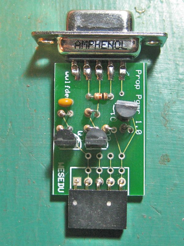
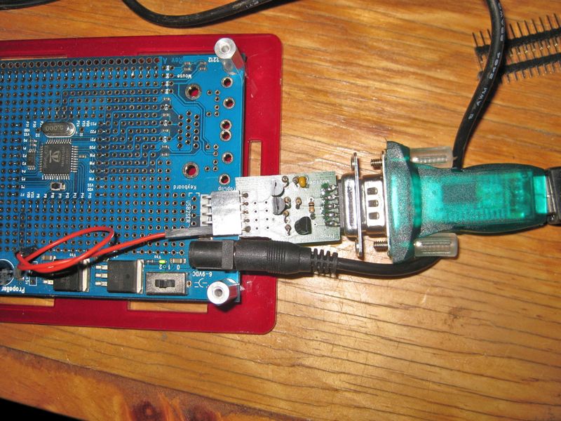
P1 - the Propeller/Basic Stamp Programming Adapter (rev 1.0)
- A simple programming adapter for the Parallax Propeller chip using discrete components and an RS232 interface. The circuit
is based upon a Parallax design widely distributed on the Parallax Propeller Forums
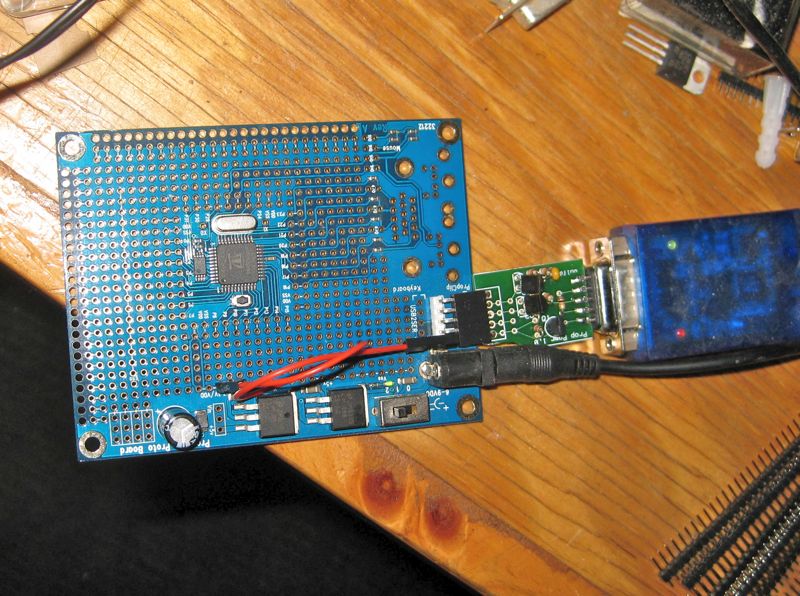
- The pinout of the P1 emulates the Prop Plug with the addition of a fifth pin to the left of the RxD line to bring 3-5 volts
power in. See picture above where it is used on a Propeller Proto Board, plugged into the 4 Prop Plug pins and a jumper is run
from he 5th socket pin to a 3.3v while on the proto board. The WulfdenPRC Rev 2.xx is already setup to use this adapter
- Also can be used to interface to home built Basic Stamps using Parallax OEM chips... have a BS2 at less than one-third the price
- Readily works with almost any USB-to-Serial adapter. The only caveat is that it must support simple control of DTR
- Top quality double sided PCBoard, with solder mask and silkscreen
- Kits and assembled units come with a 5 pin right angled socket header emulating the Prop Plug interface and a 5 pin straight
male header for breadboard interface. Your choice decided at build time.
- Easy, illustrated assembly instructions. It goes together in 10 minutes.
- The schematic is available.
- To purchase a P1 see below
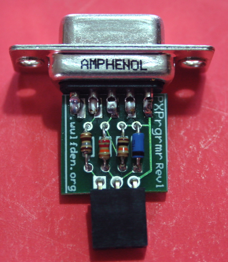
P2 - the PXProgrammer (rev 1.0)
- a simple enhanced (with protective diode on Sin and series limiting resistor on Sout) PICAXE programming interface
- Top quality double sided PCBoard, with solder mask and silkscreen
- Readily works with any USB-to-Serial adapter.
- easy assembly, goes together in 5 minutes see instructions and pix below
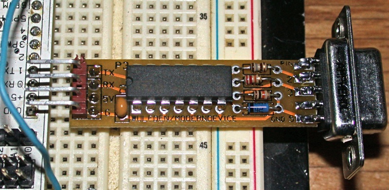
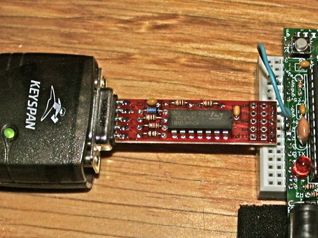
P3 - Serial TTL-to-RS232 Adapter/Programmer (rev 1.0)
- The P3 was developed jointly by Wulfden and Modern Device Company (of Providence, RI)
- A simple and inexpensive RX/TX serial programming adapter, useful to interface TTL i/o lines to external RS232
- Top quality double sided PCBoard, with solder mask and silkscreen
- runs on 3.3 to 5volts
- RS232 input and output protected with current limiting resistors and a diode
- Two sets of 4-pin holes flexible choice of interfacing to a solderless breadboard (see pix to left) or conventonal sockets
- easy assembly, goes together in 5 minutes see instructions and pix below
- A complete manual with pictures, parts list, assembly instructions, schematics, etc P3 and P4 Serial Adapters
- 2.4 MB - last updated on [an error occurred while processing this directive]
- While the unit can be used with any processor, the pinout (GND, +Vdd, RX, TX) matches for direct plugin as a programming adapter on a breadboard to the
Wulfden Freeduino Kit or a
Modern Device Bare Bones Board Kit
- For quantity pricing not listed below
contact us by email.
|
Propeller Plug - Parallax p/n: 32201 - Propeller Plug, comes with retractable USB type A to mini-B cable
|
|
$15
|
|
USB-BUB - FTDI based USB to TTL serial programming adapter. Electrical and software interface is identical to
the FTDI TTL-232 cable. Requires USB cable with miniB end. More details on the BUB are here.
|
 |
Basic Arduino BUB - FTDI based USB to TTL serial programming adapter. Electrical and software interface is identical to
the FTDI TTL-232 cable.
|
Ard-BUB
$14
|
w/cable
$16
|
|
Multi-BUB Kit - comes with two Multi-BUB adapter boards and an assortment of possible header connectors to
adapt the BUB for other platforms than Arduino. i.e Parallax Propeller, DorkBoards, Picaxe, Basic Stamp, so user can configure
to his needs.
|
$5
|
|
Multi-BUB Kit Bundled with a BUB
|
Multi-BUB+
$18
|
w/cable
$20
|
|
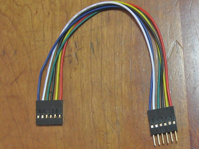
6"/6 pin Male to Female BUB extender cable
- .100" spaced male and female sockets (Molex KK). Can serve
as an extension cable for the BUB and many other things as well.
|
Qty=1
$3
|
Qty=3
$7
|
|
U2 - a PL2303 based USB (2.0) to RS232 adapter dongle, with extension cable and driver diskette.
For more info see above
|
Qty=1
$10
|
Qty=3
$24
|
| |
P1 Kit |
| P1 - Propeller/Basic Stamp Programming Adapter |
Qty=1
$5
|
Qty=3
$14
|
| P1 - bare PCBs |
Qty=1
$3
|
Qty=3
$6
|
| |
P2 Kit |
| P2 - PXProgrammer |
Qty=1
$3
|
Qty=3
$8
|
| |
P3 Kit |
| P3 - TTL-to-RS232 adapter/programmer |
Qty=1
$3
|
Qty=3
$8
|
| P3 - bare PCBs |
Qty=1
$1
|
Qty=5
$4
|
| |
P4 Kit |
P4 - TTL-to-RS232 adapter/programmer w/DTR Support
The P4 is available in limited
quantities primarily for use with the Dorkboard where it can be used with
no rewiring. We recommend the P4B (below) for general Arduino/Freeduino use. |
Qty=1
$5
|
Qty=3
$13
|
| P4 - bare PCBs |
Qty=1
$2
|
Qty=5
$8
|
| |
P4b Kit |
P4b - TTL-to-RS232 adapter/programmer w/DTR Support
The P4B is the
recommended TTL-RS232 adapter for general Arduino/Freeduino use. |
Qty=1
$5
|
Qty=3
$13
|
| P4b - bare PCBs |
Qty=1
$2
|
Qty=5
$8
|
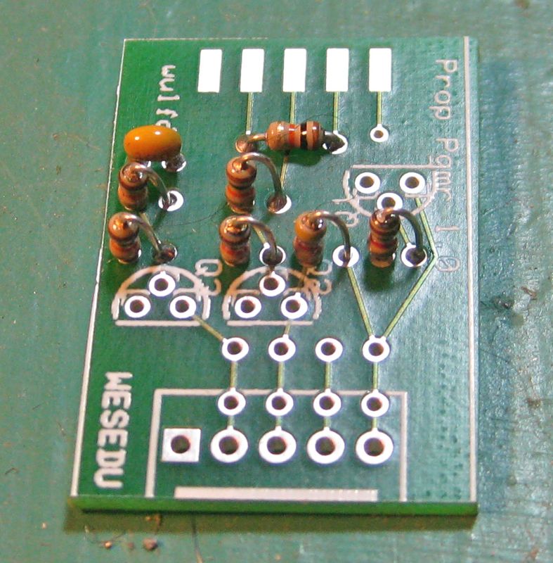
P1 - Assembly Instructions
|
- Referring to the picture to the left. (It may be enlarged by clicking on it)
There are seven resistors and one capacitor all but one resistor go in vertically.
- 5 - 10 Kohm (brown-black-orange)
- 1 - 4.7 Kohm (yellow-violet-red)
- 1 - 1 Kohm (brown-black-red)
- 1 - 0.1 uF, yellow bead
- From left to right insert the following:
- On the left two 10 Kohm resistors vertically and then the 0.1 uF monolithic cap. Solder and clip excess leads
- Next to the left, two 10 Kohm resistors, Then a third 10 Kohm resistor is mounted horizontally. Solder and clip leads
- Next to the right, insert a 4.7 Kohm resistor vertically, then solder and clip
- All the way to the right, insert a 1 Kohm resistor vertically, then solder and clip
|
|
|
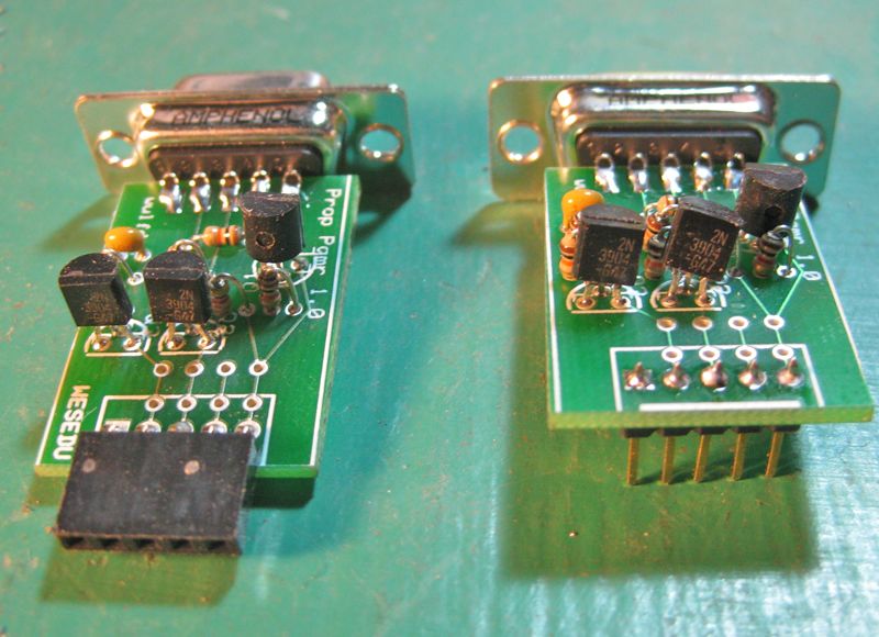
- There are three transistors
- 2 npn - 2N3904
- 1 pnp - 2N3906
- Referring to picture at left. Using the outlines as a guide, from left to right insert the following:
- the two 2N3904s go into the left and middle places facing the programming connector
- the 2N3906 goes into the right place facing the DB-9 connector
- Push the DB9 plug pins over the edge of the boards. On some of the boards they do not line up perfectly but well
enough that they can be soldered on without making any unwanted solder bridges. There is a tendency to foget to
solder the bottom pins 6-9 since they have no connectios. DO SOLDER pins 6-9, they contribute greatly to the
mechnaical strength of the DB9 to pcb connection.
- Attach the 5 pin female socket header and solder. If this board is going to be used just for breadboard work,
you may wish to substitute a 5 pin, straight up header section, inserting it from the solder side of the board
with the long pins down, and soldering on the top side.
- Please take note of the double row of 4 holes immediately above the holes for the
J5 connector. Nothing goes into these holes under most circumstances. However if you have reason to rearrange the
i/o signals and voltage input, you may cut these four traces and solder in jumper wires to make t he connections
as you like
|
P2 - Assembly Instructions
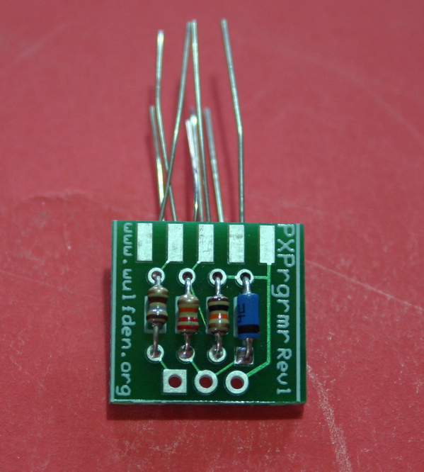
- Insert the three resistors. From left to right 180 ohms (briwn-gray-brown), 22 Kohms (red-red-orange, 10 Kohms (brown-black-orange), then the BAT42
Diode (black band down) - see figure #1
- The next steps may seem tedious for what looks so simple. The PCB here is very small and everything is on it compactly. These steps are designed
to allow you to solder both the leads and the DB9 connectors down in close proximity with the least chance of creating an unwanted solder bridge.
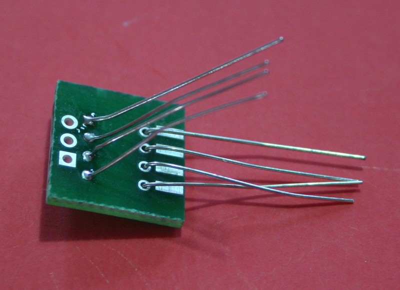
- Bend leads as shown in figure #2 with one set of leads away from the edges.
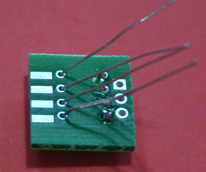
- Solder and clip these leads. Bend the remaining leads away from the edge as in figure #3. Solder and clip them also
- Push the DB9 plug pins over the edge of the board. On some of the boards they do not line up pefectly but well enough that they can be soldered
on without making any unwanted solder bridges.
- Attach the 3 pin female socket header and solder. If this board is going to be used just for breadboard work, you may wish to substitue and 3 pin,
straight up header section, inserting it from the solder side of the board with the long pins down, and soldering on the top side.
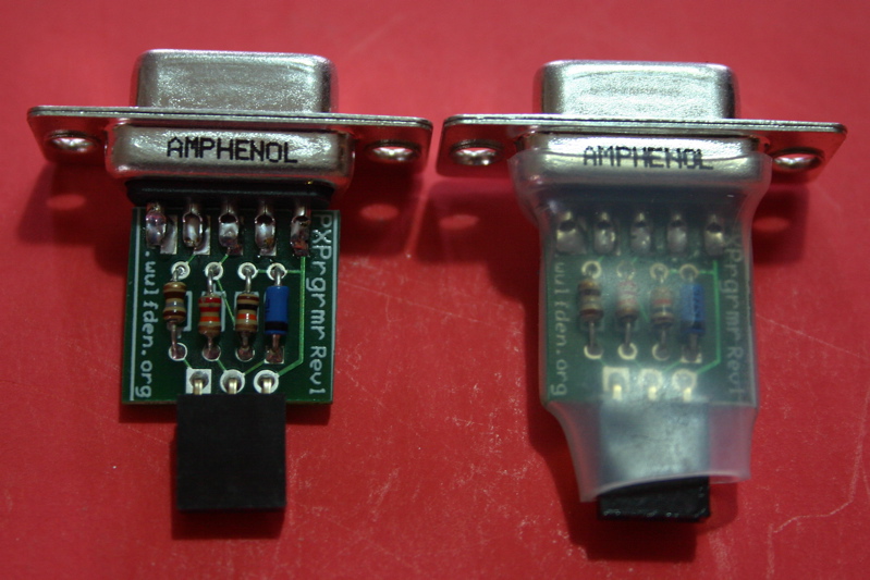
- Slide the clear heatshrink over the unit and gently heat with a heat gun or over a stove. Hold unit with forceps or hot dog tongs and keep it moving
so as not to damage the board or plastic connectors
- The Pinouts of the P2 header connector as as follows. Holding the P2 with the socket header towards you and the DB9 away. (refer to figure #1)
Left to right, Pins 1(square pad), 2, & 3;
- Pin 1 - Sout
- Pin 2 - Sin
- Pin 3 - Gnd
- Note - Rev-Ed leaves the 10K/22K resistors in place after programming. This keeps the Sin pin from floating
and falsely invoking the bootloader. Since the P2 has them on its board and they will be removed after programming, you can install as part of the permanent
target chip circuit design a 47K (yellow-violet-orange) 1/8watt resistor from the Sin pin to GND. When the 10K/22K divider from the P2 is placed across this
it will have no adverse effect on the programming process, but when the P2 is removed the 47K resistor will hold the Sin pin down and out of trouble.
[Click on any picture below to enlarge]
P3 - Assembly Instructions
- Schematic available
- Holding the board with the solder tabs towards you, from right to left insert the three resistors; 180 ohms (brown-gray-brown),
22 Kohms (red-red-orange, 10 Kohms (brown-black-orange), then the BAT42 Diode (black band towards chip)
- solder and clip these leads off
- Carefully lay the chip on its side and push it evenly from both sides so the legs are more perpedicular to the chip rather than splayed outward
as it comes from the factory. Then turn the chip on its other side and do the same
- Align the chip with its notch towards the two rows of 4 holes end. (if you hold the PCB so you can read the words "Wulfden/ModernDevice", then
the writing on the chip will be upside down). Now carefully insert the chip into the 14 holes.
- check that all pins are through their respective holes, bend a two pins over at diagonally opposite points to hold the chip in place while you solder.
- Solder and clip these leads.
- Push the DB9 plug pins over the edge of the board. With some of thses connectors they do not line up absolutely perfectly but well enough that they
can be soldered on without making any unwanted solder bridges.
- insert, solder, and clip lead of the .01 uF capacitor (marked "104")
- Insert the connector of choice, pins, sockets, wires. You may use either or both of the two sets of four holes
- The Pinouts of the P3 header connector as as follows. Left to right, Pins 1(square pad), 2, 3, & 4;
- Pin 1 - TX (data to RS232)
- Pin 2 - RX (data from RS232)
- Pin 3 - + 3.3-5.5 vdc (power from host)
- Pin 4 - GND
[Step-by-Step Pictures to come]
P4 - Assembly Instructions
- Schematic available
- Holding the board with the solder tabs towards you, from right to left insert the three resistors; 180 ohms (brown-gray-brown),
22 Kohms (red-red-orange, 10 Kohms (brown-black-orange), then the BAT42 Diode (black band towards chip)
- solder and clip these leads off
- Along the left edge insert a 0.1 uF cap (marked "104"), the two 10 K resistors, and another 0.1 uF cap, solder, and clip excess leads
- Carefully lay the chip on its side and push it evenly from both sides so the legs are more perpedicular to the chip rather than splayed outward
as it comes from the factory. Then turn the chip on its other side and do the same
- Align the chip with its notch towards the three rows of 5 holes end. (if you hold the PCB so you can read the words "Wulfden/ModernDevice", then
the writing on the chip will be upside down). Now carefully insert the chip into the 14 holes.
- check that all pins are through their respective holes, bend a two pins over at diagonally opposite points to hold the chip in place while you solder.
- Solder and clip these leads.
- Push the DB9 plug pins over the edge of the board. With some of thses connectors they do not line up absolutely perfectly but well enough that they
can be soldered on without making any unwanted solder bridges.
- Insert the connector of choice, pins, sockets, wires. You may use any of the sets of five holes.
- You may also cut the traces between the two rows closest to the chip and then use those two rows and short wire jumpers to re-align the pinouts
- The Pinouts of the P4 header connector as as follows. Left to right, Pins 1(square pad), 2, 3, 4, & 5;
- Pin 1 - TX (data to RS232)
- Pin 2 - RX (data from RS232)
- Pin 3 - + 3.3-5.5 vdc (power from host)
- Pin 4 - GND
- Pin 5 - Reset
[Step-by-Step Pictures to come]
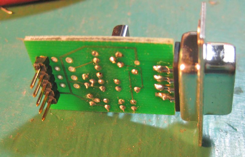
P4 with LilyPad Arduino(R)
_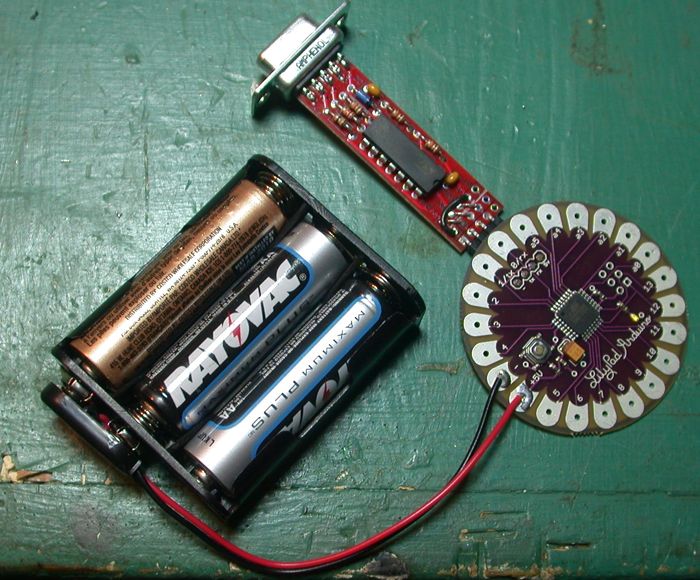
Lilypad Arduino. P4, and 4.5 volt batterypack |
_
Closeup of rewired pin arrangement |
_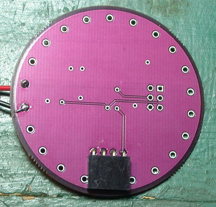
Bottom mounted socket header for clean connection |
|